
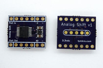
 Analog Shift
This is a digital to analog converter. It takes a 7-bit digital value from 0000000 to 1111111 & converts it to a voltage between 0V to 3.3V
This board is. Really. Cool. It is a digital to analog converter that doesn’t use a DAC chip! It can take any 7-bit digital value from 0000000 to 1111111 and convert it to a voltage between 0V and 3.3V. But it is also compatible with shift registers and so it can accept 8 bits as well. The analog out is based on the lower 7 bits.
Kit Parts:
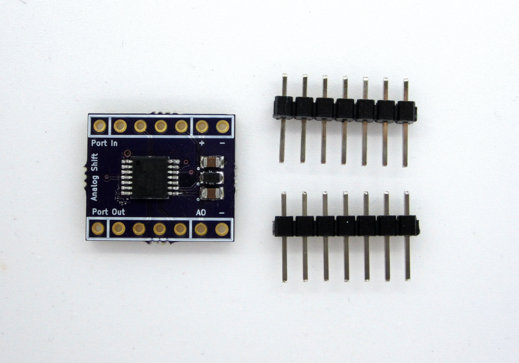
- Populated PCB - the PIC chip will be pre-flashed with the firmware.
- 2x 1×7 right angle female header
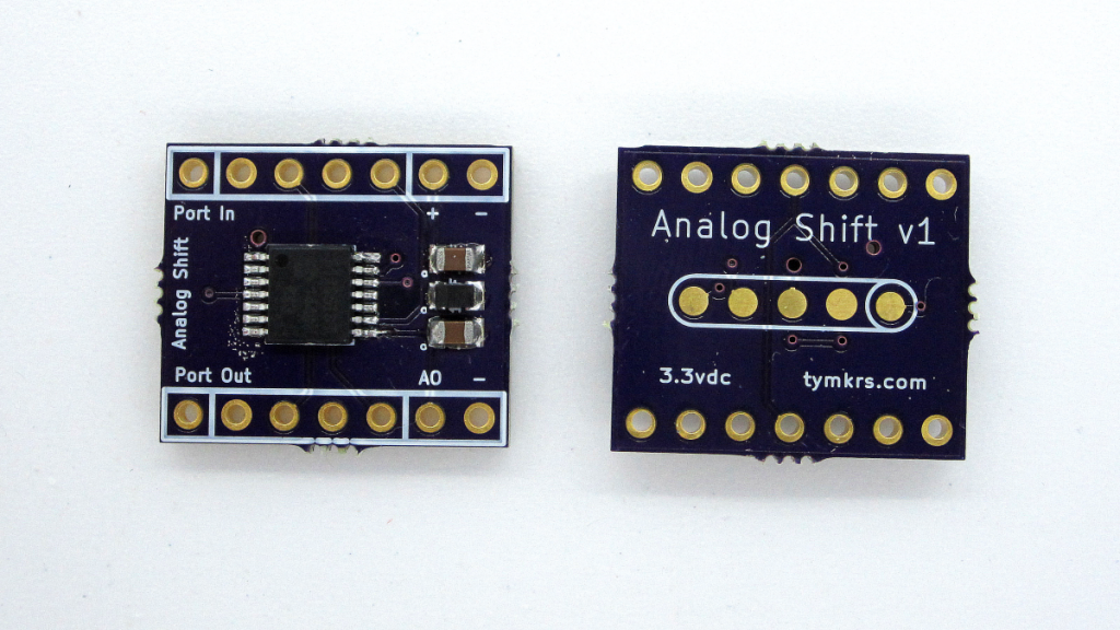
- Port In Chaining Header: From left to right, Power, GND, Clock, Latch, and Data In (digital) - this is the chainable power/data bus. Whatever you put in here, can be daisy chained via the Port Out Chaining Header.
- Auxiliary + / - (on the Port In side): This is an additional power header which allows you to put a separate power supply for the board in the event that you are chaining multiple boards and would like to provide more amperage/higher current.
- In one use case, you would use the chaining headers to power this board and an additional one and you would use the auxiliary header to power whatever is hooked onto the board (if it needs 3.3 volts).
- In another use case, you would use the ground connection of the chaining headers but you would leave the Power unconnected. You would then connect an external power supply to the auxiliary power header making sure that the ground of that power supply was hooked into this GND. But remember, the voltage has to be 3.3V. You would use this auxiliary power port if you were running MANY of these modules and you needed larger amperage capacity that could only be supplied by an additional power supply.
- Port Out Chaining Header: From left to right is Power, GND, Clock, Latch, and Data Out (digital).
- AO: This stands for Analog Out. This is the 0 to 3.3V DAC value that is given when you put in your data.
- - (on Port Out side): This GND connection is used for connecting to the same ground as the target circuit that the Analog Out voltage would go to.
- Please note that all 4 GND connections are connected to the same ground plane.
-
1. Set your LATCH, CLOCK, and DATA pins on your microcontroller (or however you’re driving it) as Outputs
2. Set your CLOCK and LATCH pin to LOW
3. Set your DATA pin to the value of the least significant bit. (Bit number 0 assuming we’re going 0 to 7)
4. Set your CLOCK pin to HIGH and then to LOW
5. Repeat this process for all 8 bits.
6. Set your latch pin to HIGH and then to LOW
7. The analog voltage will then change on the output.
- The analog out is based on the lower seven bits (bits 0 to 6 assuming we’re inputting 8 bit value 0 to 7).
- At 3.3V the drive current is solid out to about 70mA
- Propeller Microcontroller: http://tymkrs.com/code/AnalogShiftDemo.spin
