
 NPN8 Module
This allows you to control 8 NPN BJT transistors from one serial to parallel shift register to drive higher current loads.
We wanted to make shift registers dead easy to use - whether for LEDs, or audio purposes, or to control 8 items simultaneously with 1s and 0s, this assembled NPN8 module is it! This allows you to control 8 NPN BJT transistors from one shift register. The 1/0s act as bias for the bases of the transistors. The current load is higher for this board than for the TTL8 board.
Kit Parts:
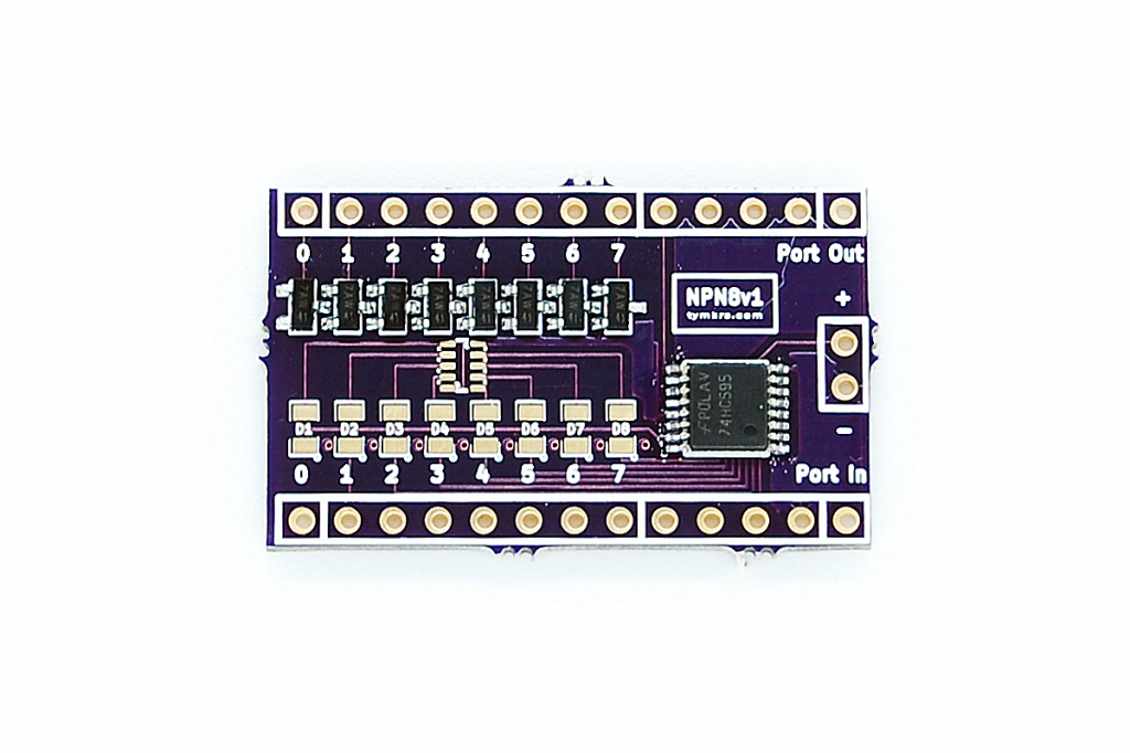
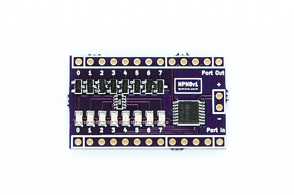
- Assembled NPN8 module with OR without indicator LEDs
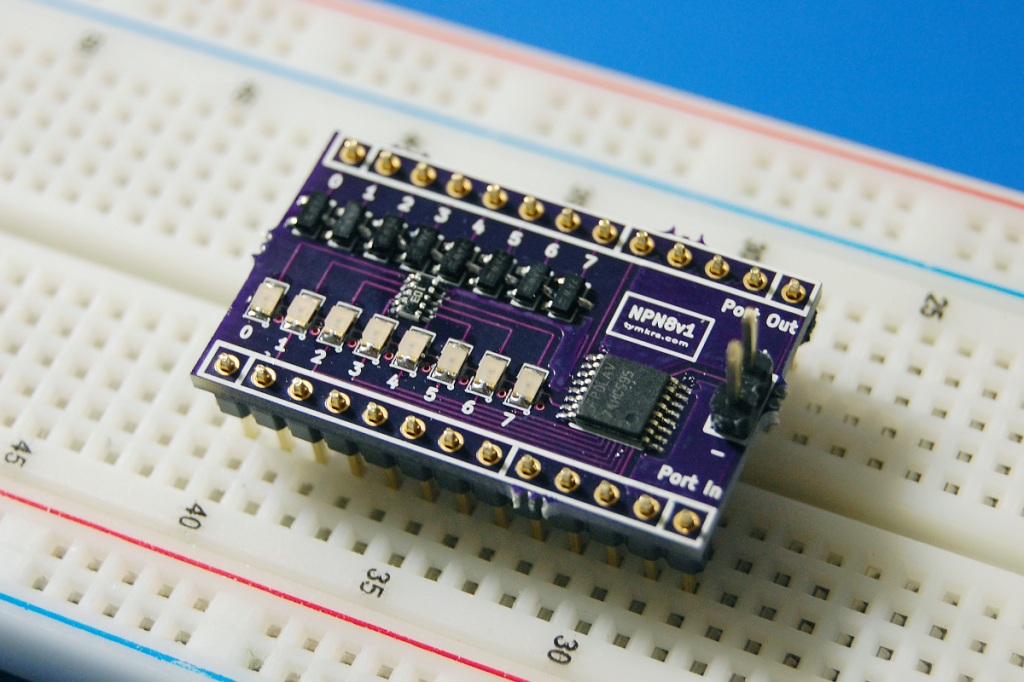
- Male headers if you choose to use them.
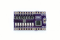
- With Port In on the bottom right, from right to left, it’s Power -> GND -> Clock -> Latch -> Serial
- On the Port Out side, from right to left it’s Power -> GND -> Clock -> Latch -> Serial
- The 0-7s on the Port In side are connected to the transistor’s emitters
- The 0-7s on the Port Out side are connected to the transistor’s collectors
- We have tested this successfully with 3.3v.
- The Port In side is where you would connect the microcontroller in - the NPN8 board should share the same ground as the microcontroller. But the microcontroller doesn’t have to power the NPN8 board.
- You can use the power headers on the right side of the board to power the shift register BUT the voltage between the microcontroller and the NPN8 board must be the same. IE if your microcontroller runs off of 3.3v, your board needs to be powered with 3.3v. This is due to the comparator in the shift register which determines what a 1 and what a 0 is.
- The Port Out side is used for daisy chaining to more NPN8 boards so if you wanted 32 items controlled, you could do that.
So if you wanted to run 8 LEDs from this board, you would connect the cathodes of the LEDs to the collectors of the transistors (Port Out). All of the emitters of the transistors (Port In) connect to ground. All of the anodes of the LEDs connect to a power source.
When the 595 shift register brings the pin for that transistor’s base HIGH, it allows current to go from the collector to emitter. So power goes from the devboard, through the LED, through the transistor (collector to emitter), and then to ground.
Demo Code: http://pastebin.com/FmiHMVmm
New to shift registers? Not sure how to use them?:
http://tymkrs.tumblr.com/post/53522451066/tymkrs-shift-me-chainable-shift-register-header-kit
